An (almost) perfect home automation solution: A Build Log
I usually start at the start - but that will take a long time. And the challenges that have been already overcome are not as interesting as the ones that I’m working on now.
Background
The most basic premise of “home automation” is very simple - I should be able to control a switch using a computer. This implies that the switch
must be controlled by a relay, the relay must be controlled by a microcontroller and the microcontroller, in turn, must connect to awireless network. If we can get this to work reliably and conveniently, then we can do so much more beyond that.


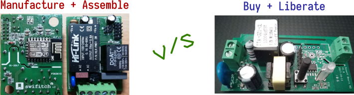
The idea is to source off-the-shelf wireless switches and liberate them by flashing free software, privacy-respecting firmware on them. A Raspberry Pi 4 running Home Assistant, an MQTT server and more such backends completes the ecosystem.
The advantage of repurposing and liberating such boards over manufacturing custom boards is that it gives us low costs, good quality and the quick sourcing timelines.
Primary Goal: Make it easier to deploy
The liberated mhsw switch run the Espurna firmware. Its mirrored here for our development.
The default workflow for integrating an Espurna powered wireless switch into your home infrastructure is:
- to power it on (via mains),
- connect to its wireless access point, and
- login to the built-in web interface.
After that one would configure the following parameters:
- Credentials of your local wireless network
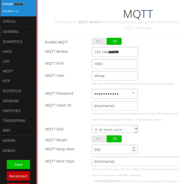
- Connection and login details of the local MQTT server
- Password for the web interface
- Home Assistant (HASS) settings
- … and more.
If this looks simple enough to do for 1 device, imagine doing this for all the 10 devices to be deployed around your home. It would be tough, time-consuming and frustrating.
How can we make this process easier? Two simple ways:
Custom compile Espurna with all the settings pre-configured
Espurna configuration can be customised by changing a single header file and recompiling the code using PlatformIO.
For example:
#define DEVICE_NAME            "mhsw_" DEVICE     // Concatenate both to get a unique device name
#define ADMIN_PASS             "FreeAsInFreedom"  // Default password (WEB, OTA, WIFI SoftAP)
#define RELAY_BOOT_MODE        2
#define WIFI_AP_SSID           "LibreTechShop"     // (optional) Specify softAp SSID.
#define WIFI1_SSID             "MostlyHarmless"
#define WIFI1_PASS             "wifi_password"
#define WIFI2_SSID             "MH_EXT"
#define WIFI2_PASS             "wifi_password"
#define WEB_FORCE_PASS_CHANGE   0  // Force the user to change the password if default one
#define MQTT_ENABLED            1               // Do not enable MQTT connection by default
#define MQTT_SERVER             "192.168.1.42" // Default MQTT broker address
#define MQTT_USER               "mhsw"         // Default MQTT broker usename
#define MQTT_PASS               "xxxxx"        // Default MQTT broker password
Flash the modified Easpurna firmware binary to the board
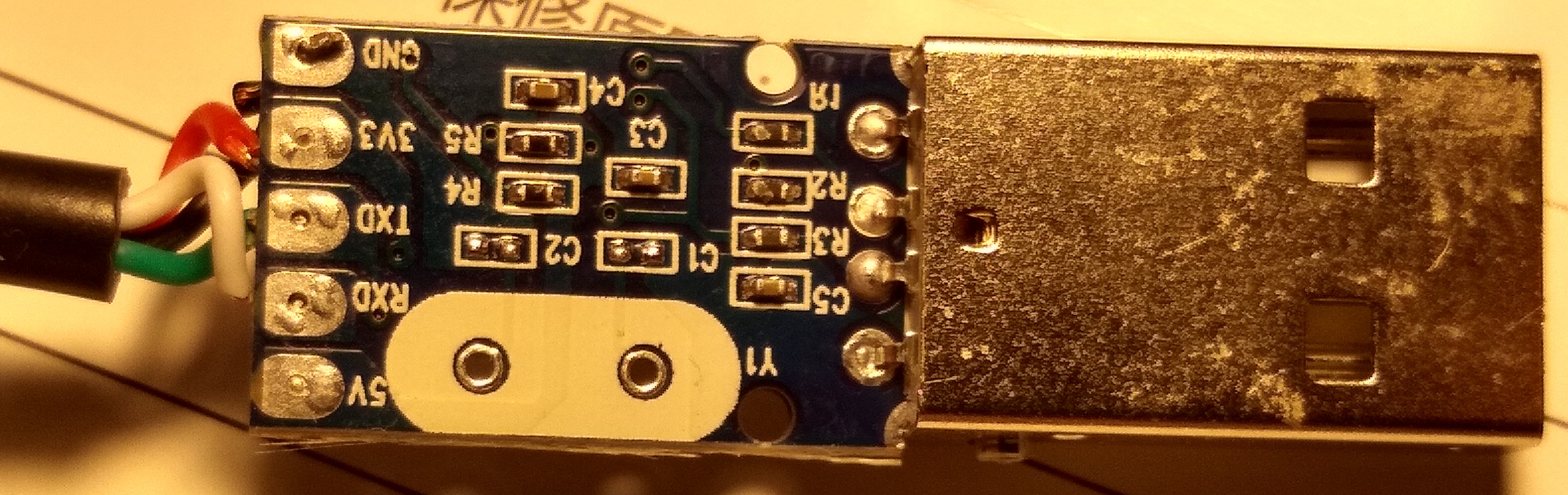
Once the binary firmware is generated, it can be flashed back to the wireless switch using a simple USB-Serial cable. Now the problem of configuring 10 devices (or 20) is so much simpler.
This is is a USB Serial programmer reconfigured to use 3v (by default it uses 5v):
Once you flash the new pre-configured firmware to each board, it will boot up and connect to your wireless network + MQTT server and will be ready to serve you.
So much time saved! Having figured this out is fine. The challenges start here… ![]()
Problem #1: Making it simple and error-free to program the board
The common way to program a microcontroller is connecting its programming pins to a programmer. This requires one to open up the switch case, align 4 programmer pins in the right manner and then upload the code.
This is cumbersome to say the least… If it took so much effort to reprogram a switch, no one would reprogram it. And then what is the point of having the source code of the firmware, if no one compiled it or flashed it back to the device?!
A hackable device should make it easier for its owner to flash new firmware onto it.
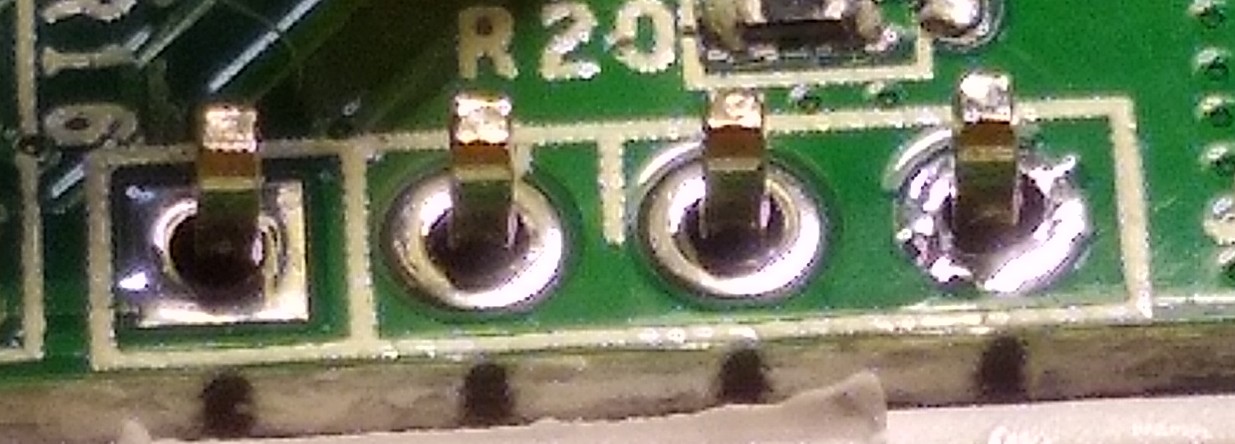
Solution Attempt #1: hackish programming pins that are “broken out”
My first attempt at simplifying this was to use extra long PCB headers, drill 4 holes right below the PCB into the case and bend the headers so that they are accessible outside the case. This is what it looked like:
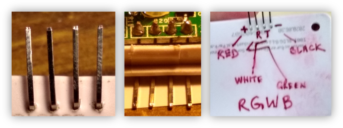
While this was functional, it was ugly. I could foresee mhsw owners wondering if 4 such pins protruding out of electrical equipment were a hazard of some sort.
Solution Attempt #2: TRRS 4-pole Audio connectors
The second attempt was to drill a hole into the case and try to integrate a 4-pole TRRS (ie. audio) female connector. The challenge with this was that there’s isn’t enough space to securely integrate this connector.
Also pushing and pulling out the TRRS required too much force and that would destabilize the connector.
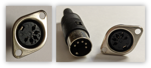
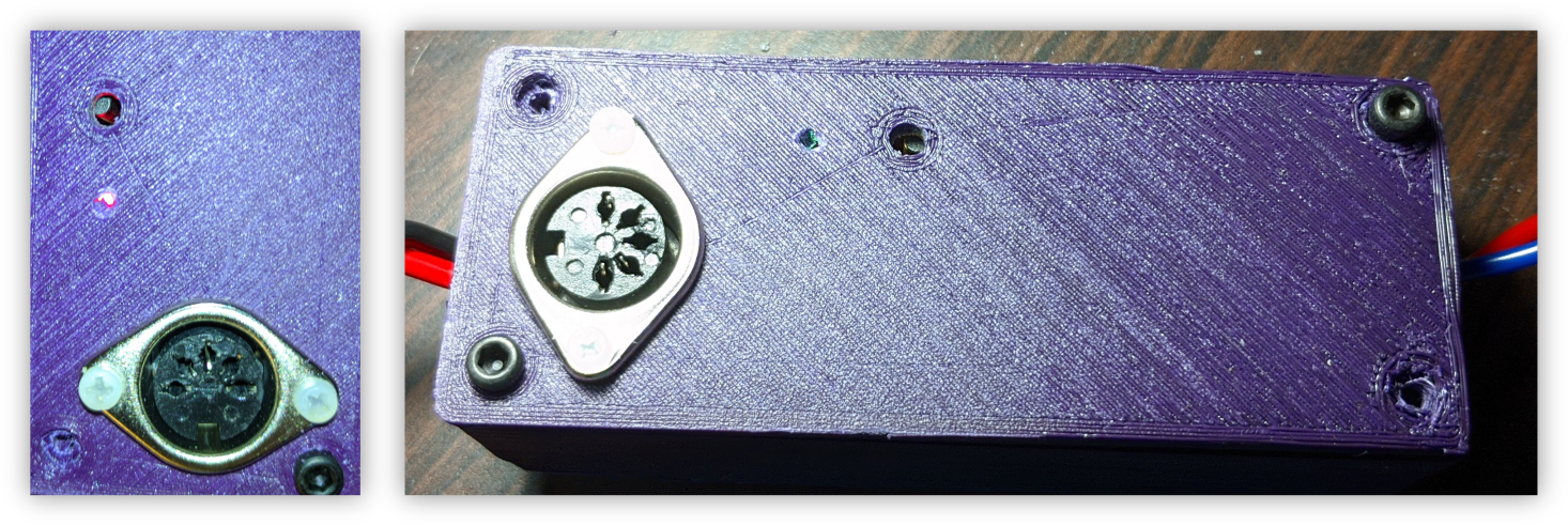
Solution Attempt #3: 3D Printed Case + MIDI Connector
My next attempt actually works. This time instead of retaining the default enclosure for the PCB, I decided that maybe I could 3D print the enclosure and maybe, the new one might be big enough to integrate a proper programming connector.
Fortunately, there are several designs on Thingiverse that can house the PCB and are big enough to host a programming connector.
For the connector, I chose a panel-mount MIDI connector:
This is easy to integrate into the new mhsw case:
The Next Step
3D Printed cases are, however, not a “production” choice. These are good options for quick prototypes. But they don’t make cost-effective enclosures or economical ones. Or good quality ones.
I am now talking to enclosure manufacturers to see how much quantity they need for me to order to use the 3D printed design as a template for a more polished and mass-produced case.
Problem #2: Make it easy to configure and compile the firmware
At the moment, pre-configuring the Espurna firmware and compiling it using the PlatformIO framework requires one to install a lot of development tools and use the GNU+Linux command-line. While that might be a good solution for experienced free software users, it won’t appeal to most people - especially if they use other operating systems.
Solution: Build a HASS add-on to configure and compile Espurna
The solution that I am attempting to build is to create an add-on for Home Assistant that will provide a web-interface to pre-configure and compile the Espurna firmware. This add-on will run on the Raspberry Pi supplied along with the “Home Automation” kit.
The HASS add-on will provide a form to input the customisable properties and then, will fire-up a Docker container to compile the firmware and make the binary available to the user.
I think it might be possible to build a similar UI for programming the board as well. So all one would need to do after compiling the firmware, is to plugin the programming cable to switch and click another button on the HASS dashboard to program the hardware.
When would it be available to purchase?
As you might have seen on the LibreTechShop, it is not possible to purchase the Home Automation kit as yet since (a) these two problems are not yet elegantly solved, and (b) there is no documentation or a manual to help owners of such a kit figure out how to use it.